
Modification of the LS-STAG Immersed Boundary Method for Simulating Turbulent Flows
ISSN 1812-3368. Вестник МГТУ им. Н.Э. Баумана. Сер. Естественные науки. 2017. № 5
31
End of Table 4
Turbulence model
Number
of cells
Re 1000
=
Re 3900
=
D
C
St
D
C
St
Smag., LES,
C
S
= 0.1 [17], ANSYS
388 550
1.15 0.21
1.07
–
Smag., LES,
max
= ,
= 0.2,
S
C
present study
71 040
1.35 0.24
1.11
0.26
Smag., LES,
max
= ,
= 0.5,
S
C
present study
71 040
1.37 0.25
1.10
0.25
S-A, RANS, present study
71 040
1.37 0.25
1.13
0.25
S-A, DES,
= 0.7,
S
C
present study
71 040
1.37 0.25
1.11
0.25
,
k
RANS, present study
71 040
1.36 0.25
1.23
0.28
,
k
LES,
max
= ,
= 0.9,
S
C
present
study
71 040
1.37 0.25
1.11
0.25
,
k
RANS, present study
71 040
1.32 0.24
1.18
0.24
,
k
DES,
=1.0,
S
C
present study
71 040
1.32 0.25
1.00
0,25
k
SST, RANS, present study
71 040
1.34 0.25
1.14
0.25
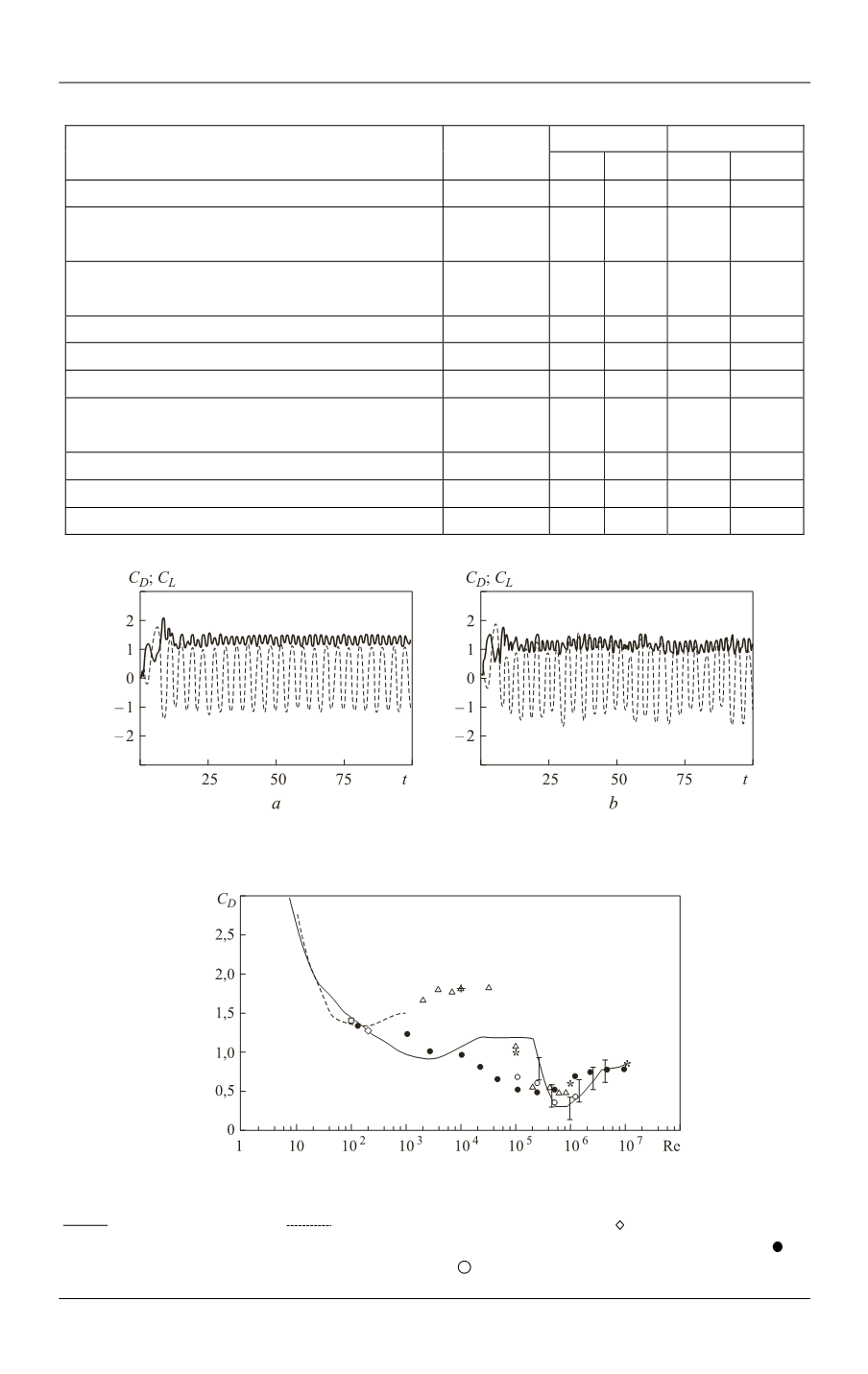
Fig. 5.
Computed unsteady load
( )
D
C t
and
( )
L
C t
(RANS,
k
model, mesh
240 296):
a —
Re =1000
;
b —
Re = 3900
Fig. 6.
Comparison of the drag coefficient computed values with experimental [18]
and computational data on meshes M1–M5 [19] and [20]:
— Wieselsberger [18]; — Henderson, 2D calculations [20]; — mesh M1; + — mesh
M2; ☐ — mesh M3; × — mesh M4 with Smagorinsky model; Δ — mesh M4;
*
— mesh M5; —
LS-STAG (
k
–
, RANS, 240×296);
— LS-STAG (480×592)


